
ACEIRMC CH341A BIOS Programmer Kit
4.4Editor score
Supports common 24 and 25 series chips
Includes 1.8V adapter and test clip
Enables backup, erase, and programming
Our Bios Programmer Kit guide compares ten USB and SPI programmers for BIOS flash, EEPROM backup, chip testing, repair, and in-circuit programming tasks.
A BIOS programmer kit gives technicians and advanced electronics users a practical way to read, back up, erase, and write EEPROM and SPI flash chips. The best kit should combine dependable chip detection, useful adapters, clear software support, and a connection method suited to the devices being serviced.
This guide compares ten BIOS programmer kits by examining supported chip families, programming controls, included accessories, voltage handling, in-circuit access, and intended repair applications. It covers both compact CH341A systems and higher-end EZP models, while also identifying listings for which detailed specifications were unavailable.
Each review explains what the available product information supports and where a buyer should verify compatibility before purchasing. The top selections reflect the strongest balance of features, ratings, and practical utility. Prices and availability can change, so confirm the current listing before placing an order.
4.4Editor score

4.3Editor score

4.5Editor score
This side-by-side comparison organizes the kits by programmer platform, supported memory families, connection accessories, and practical repair use. Products with missing listing details are included for completeness, but their compatibility should be confirmed directly with the seller.


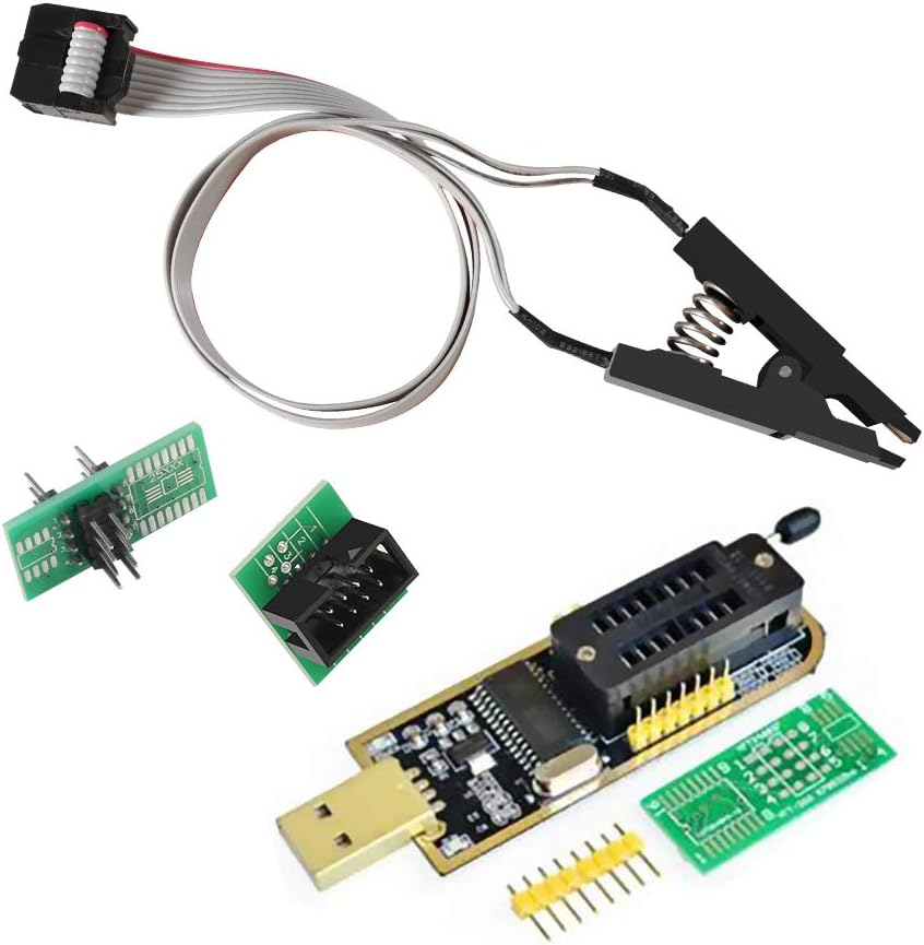


This ACEIRMC kit combines a CH341A-based USB programmer with a SOIC8-to-DIP8 adapter, an in-circuit test clip, and a 1.8V adapter. Its 4.4 rating reflects a generally favorable customer response, while the included accessories make it a practical entry point for BIOS, EEPROM, and SPI flash work. The listing specifically positions it for amateur programmers working with 24 and 25 series flash chips.
We may earn a commission when you buy through this link, at no additional cost to you.
Its strongest feature is the range of connection options. The test clip can reach a compatible SOIC8 chip while it remains mounted to a motherboard, which can make a backup or repair process less invasive than removing the package. The separate 1.8V adapter is also valuable for compatible 1.8V SPI flash memory used in motherboards and other devices, while the socket converter allows a different approach when appropriate.
The programmer uses the CH341A USB interface and supports backup, erasing, burning, checking, and repair operations. The listing states that programming can be two to three times faster than an ordinary ATMEGA8-based 25-series programmer, although actual performance depends on the chip, computer, software, and connection. It also notes a claimed erasing rate of 2–3 Mbit per minute. These are seller-provided performance statements rather than independently verified test results.
This is a sensible choice for a technician who wants in-circuit access, voltage flexibility, and several physical adapters in one purchase. It is less attractive when automatic chip identification is essential or when the exact device uses a package or voltage configuration outside the supplied description. Confirm the chip marking, package size, and operating voltage before using the programmer on a board.
The SOIC8 test clip is the kit's most repair-focused component. It can connect to compatible 24CXX, 25CXX, and 93CXX devices while they remain on a board, helping users investigate firmware, configuration, and BIOS-related memory without immediately removing the chip.
A dedicated 1.8V adapter and a 150mil SOIC8-to-DIP8 converter broaden the ways a technician can connect supported memory. These accessories are especially relevant to compact motherboard designs, although physical compatibility should be checked before ordering.
We may earn a commission when you buy through this link, at no additional cost to you.
The EZP2023 is built around three automation features: identifying the chip model, detecting whether it is seated correctly, and selecting the appropriate supply voltage. Those functions make it one of the more approachable programmers in this roundup. The supplied 4.3 rating indicates a solid customer reception, and the product supports 25-series SPI flash as well as 24, 25, 93, and 95-series EEPROM devices.
We may earn a commission when you buy through this link, at no additional cost to you.
Automatic detection is particularly useful when handling a mixed collection of memory chips. The listing says chip placement and supply voltage are handled automatically, which reduces the number of settings a user must configure. It does, however, clarify that certain EEPROM devices still need to be selected manually, so the software's supported-device list should be checked before a job begins.
Performance claims include reading an EN25T80 in three seconds and writing it in nine seconds. These figures are especially attractive for repair and production workflows, although they are not guarantees for every chip or computer. The offline copy function also makes the programmer more suitable for batch work by allowing a read image to be reproduced without repeating the source operation for every device.
The EZP2023 is a strong general recommendation for users who want automation and broad chip-family coverage without moving to a much larger professional platform. It is particularly relevant to motherboard, television, DVD, and appliance repair. Confirm the chip identifier and package format in the software list, and verify that the included adapter matches the target device.
Automatic model, placement, and voltage detection minimize guesswork when moving between supported chips. This makes the EZP2023 more approachable for occasional users while remaining useful in production-like batch programming environments.
The offline copy feature lets a technician preserve one known image and reproduce it across compatible chips. That can streamline repair inventories and controlled product-development testing when identical firmware images are required.
We may earn a commission when you buy through this link, at no additional cost to you.
This EZP2023 Universal kit stands out with a 4.5 rating, the highest documented rating among the products for which ratings are available. It supports 25-series flash and 24-, 25-, and 93-series EEPROM chips. Automatic chip-model recognition, placement detection, and voltage selection make the programmer well suited to both individual repair work and controlled batch programming.
We may earn a commission when you buy through this link, at no additional cost to you.
Its offline copy function is the defining feature for users who need to repeat a known firmware image across multiple devices. The listing specifically identifies factory batch programming as a suitable use, while also noting use in product-development testing. It also supports PC software and programmer firmware upgrades, which can make the tool more adaptable as a technician's workflow expands.
The range of listed applications includes color televisions, DVDs, computer motherboards, and hard disks. That breadth suggests a useful general-purpose platform rather than a single-device accessory. Still, the product data does not provide the same detailed adapter inventory and explicit speed figures as the other EZP2023 listing, so buyers should confirm which physical adapters arrive in the package.
This kit earns the premium recommendation because it combines strong customer feedback, automatic setup, and a workflow feature designed for repeated programming. It is an attractive choice for repair professionals, repair shops, and technically experienced users who will program more than one chip. Before purchasing, verify the package contents, required software, operating system support, and the exact chip model list.
The offline copy function allows a verified source image to be reproduced across compatible memory chips. That is useful in factory programming and product-development testing, where consistency matters more than treating every chip as a fully manual task.
Model recognition, placement detection, and voltage selection can prevent avoidable mistakes. The system still requires the technician to use the correct socket or adapter, but it removes several common configuration steps.
We may earn a commission when you buy through this link, at no additional cost to you.
The EZP2019 is a well-established general-purpose SPI and EEPROM programmer with a 4.4 rating. It uses a USB 2.0 interface advertised at up to 12 MBPS and includes automatic chip identification, placement detection, voltage selection, and an offline copy function. Its accessory set includes several SOP8 and SOP16 sockets, a test clip, a 1.8V socket, and a USB cable.
We may earn a commission when you buy through this link, at no additional cost to you.
The strongest feature is the unusually detailed supported-chip list. It names devices from MX25L and MX25U families, Nexflash, PMC, Saifun, Spansion, SST, GigaDevice, ST, Winbond, Atmel 24-series EEPROM, and Atmel 93-series EEPROM. For a technician who regularly encounters mixed manufacturers and part numbers, this breadth can be more valuable than a small, narrowly defined kit.
The listing states that an EN25T80 can be read in roughly three seconds and written in about nine seconds. It also identifies Windows 7 and Windows 8 as supported work systems. Those operating-system details deserve attention for owners of newer computers, since the listing does not provide the same level of current-platform guidance as a modern software support page might.
The EZP2019 is well suited to experienced repair users who want one programmer to cover many SPI flash and EEPROM devices. Its physical accessory variety also reduces the need to source separate sockets for different package sizes. Before buying, compare the exact part number in your device with the supplied list and check whether the bundled software and driver expectations fit your computer.
The listed MX, Nexflash, PMC, Saifun, Spansion, SST, GigaDevice, ST, Winbond, and Atmel devices provide exceptional breadth. Users can match the full chip marking against the list before assuming programming support.
The included sockets cover several SOP8 and SOP16 dimensions, while a 1.8V socket and clip support different connection methods. This variety makes the kit easier to adapt to a mixed repair bench.
We may earn a commission when you buy through this link, at no additional cost to you.
This CH341A kit is designed around a USB programmer, SOP8 test clip, and supporting adapters for 24- and 25-series EEPROM and BIOS flash chips. It receives a 3.0 rating, which is lower than the other documented options, but the supplied information still presents a straightforward repair kit centered on backup, erase, and programming operations.
We may earn a commission when you buy through this link, at no additional cost to you.
The no-soldering test-clip approach is the main convenience. A technician can connect to a compatible in-circuit SOIC8 chip, read its current contents, and perform supported programming tasks without immediately desoldering the device. The listing says the kit supports 1.8V, 3.3V, and 5V output levels, giving it flexibility across several common device classes.
The programmer is based on CH341A or CH341B hardware and connects through USB 2.0. That platform is widely used for compact electronics programming, but users should understand that feature support depends on the underlying hardware, the supplied software, and the specific chip. Unlike the EZP models, this product does not advertise automatic model identification or automatic voltage selection.
The kit is best for a user who values physical access and a straightforward repair setup more than extensive automation. Its lower rating is a reason to inspect recent customer feedback carefully, particularly regarding software setup and chip compatibility. Verify that the target memory is supported, that the correct voltage is selected, and that surrounding circuitry will not interfere with in-circuit readings.
The included SOP8 clip allows a compatible chip to be connected while it remains mounted. This can speed up initial inspection and reduce the need to remove parts before a basic read can be attempted.
Support for 1.8V, 3.3V, and 5V output covers several common flash configurations. The correct level still must be matched to the target chip, and in-circuit use can be affected by external components.
We may earn a commission when you buy through this link, at no additional cost to you.
This ACEIRMC package combines a CH341A 24- and 25-series programmer with a double set of SOIC8 test clips. The 4.4 rating places it among the stronger customer-rated options. Its focus is in-circuit EEPROM and flash programming, making it particularly relevant to technicians who want to inspect or repair chips without immediately removing them from a board.
We may earn a commission when you buy through this link, at no additional cost to you.
Two clips offer practical value on a busy bench. One can remain connected to a target board while the other is used for a different package, device, or workspace arrangement. The kit is described as supporting common 24-, 25-, and 93-series devices, with programming functions that include backing up, erasing, programming, calibrating, and related memory operations.
There is an important compatibility caveat in the supplied information. Due to a CH341A hardware characteristic, ESMT SST class 25 chips can reportedly be read but not written. The listing also warns that some chips cannot be clipped directly because nearby peripheral circuits affect the connection. These limitations should be considered before selecting it for a specific repair.
This is a good match for a repair technician who wants two clips and a 4.4-rated CH341A setup for common SOIC8 devices. It is less suitable when ESMT SST writing is required or when a target board's layout prevents a reliable test-clip connection. Inspect the chip location and nearby components before ordering or beginning an in-circuit procedure.
The double-clip arrangement allows a technician to keep more than one connection option available. That can be useful when moving between boards or when a second clip is preferable for a different contact angle.
The product data states that ESMT SST class 25 chips can be read but not written through the CH341A platform. Users whose work depends on writing those devices should choose a programmer with verified support instead.
We may earn a commission when you buy through this link, at no additional cost to you.
The supplied data for ASIN B09DVMQTTH does not include a product title, rating, image, price information, or description. As a result, there is not enough verified information to compare this listing's hardware platform, supported chip families, software, or included accessories with the other nine products. The listing is retained here because every product source must appear in the comparison.
We may earn a commission when you buy through this link, at no additional cost to you.
Its ASIN and Amazon URL provide a concrete way to investigate the item, but any conclusion about compatibility would be speculative. A buyer would need to examine the live product page for the exact programmer model, operating-system requirements, supported memory list, voltage options, and included socket or clip accessories. Those details should be confirmed with the seller if the page is unclear.
A listing with limited visible information can still be appropriate when it is known to support a particular rare device or chip. Conversely, buying without that verification can lead to an unusable tool, missing adapters, or software that does not install correctly. For those reasons, the product should not displace a well-documented kit merely on the basis of its position in the original list.
This review therefore recommends only a compatibility-first approach: identify the exact target chip, confirm the programmer's documented support, and verify the accessories and software before ordering. If the live listing provides complete and favorable details, it may become a viable option. Until those facts are available, treat it as an unverified alternative rather than a top selection.
Check the exact chip part number, package type, voltage, and required software. A programmer that lacks a documented match for the target device should not be selected regardless of how the listing is categorized.
Absent specifications should not be interpreted as either compatibility or incompatibility. Ask the seller for supported-chip documentation, package contents, and operating-system guidance before making a purchase.
We may earn a commission when you buy through this link, at no additional cost to you.
No title, description, rating, or image details were provided for ASIN B0C7LRF3M2. This leaves the programmer's platform, supported chip types, included adapters, and software requirements unknown. It appears in this review solely to preserve a one-entry-per-product comparison and should be considered an unverified listing rather than a fully characterized recommendation.
We may earn a commission when you buy through this link, at no additional cost to you.
The available identifier and URL allow a potential buyer to inspect the current Amazon page. That is important because the live listing may contain a manual, supported-device table, package photograph, or seller response that is not represented in the source data. Those materials should establish whether the tool handles the target BIOS or EEPROM package and whether its operating voltage matches the device.
There is no verified evidence in the supplied information about automatic chip detection, socket formats, in-circuit clips, offline copy functions, or read and write speed. It would be inappropriate to attribute those benefits to this listing. A careful buyer should also determine whether the product requires a separate cable, socket adapter, or software license, as these omissions can make an apparently inexpensive programmer less useful.
Use the listing if and only if the live documentation clearly confirms the required chip, voltage, connection method, and software. If the seller can supply those details and the package includes the needed accessories, it may fit a specialized repair need. Otherwise, choose one of the better documented kits to reduce uncertainty.
Locate the complete chip marking and compare it with a current manufacturer-supported list. Similar series names are not enough because package, voltage, and command support can differ.
Ask what cables, sockets, clips, drivers, and software are included. The programmer must be usable with the user's computer and target device, not merely capable in theory.
We may earn a commission when you buy through this link, at no additional cost to you.
This two-set ACEIRMC package includes two CH341A programmers, two 1.8V adapters, two SOIC8-to-DIP8 converter modules, and two SOIC8 test clips. Its 4.2 rating is credible, although slightly lower than the related single-set listing. The defining advantage is duplication: two complete programming setups can support two technicians, two workstations, or a backup arrangement.
We may earn a commission when you buy through this link, at no additional cost to you.
Each programmer targets common 24- and 25-series flash devices and supports work such as backup, erase, burning, checking, and repair. The test clips support 93CXX, 25CXX, and 24CXX package types, while the 1.8V adapters suit compatible low-voltage SPI flash memory. The listing also mentions a broad range of equipment, including televisions, motherboards, LCD devices, routers, notebooks, cards, DVDs, and set-top boxes.
The hardware uses the CH341A USB chip with USB 1.1 communications. Seller-provided performance information says programming can be two to three times faster than an ordinary ATMEGA8-based 25-series programmer, with a stated erasing rate of 2–3 Mbit per minute. These are supplier claims, and actual results depend on the chip, file, computer, and software settings.
This package makes sense for a repair shop, classroom, or advanced hobbyist who values having two identical ready-to-use stations. If only one bench is needed, a single-set kit offers a more compact solution. In either case, confirm the target chip, package width, and voltage before buying, and avoid assuming that an in-circuit clip can always read successfully when nearby components affect the signal.
The duplicated programmers, adapters, and clips let two users work simultaneously. That is valuable in a busy shop where one device can be tested while another is programmed or investigated.
Each set includes a 1.8V adapter and a SOIC8 clip, supporting both compatible motherboard flash devices and no-desoldering inspection. The exact chip and voltage must still be checked before use.
We may earn a commission when you buy through this link, at no additional cost to you.
The RT809F package is the most specialized listing in the group, described as an EEPROM and chip programmer with eight adapters, an IC clip, and a 1.8V adapter. That emphasis on physical accessories makes it potentially useful for technicians who work across different package styles. However, the supplied data does not provide a rating, supported-chip list, software details, or performance measurements.
We may earn a commission when you buy through this link, at no additional cost to you.
An eight-adapter set can reduce the inconvenience of sourcing individual sockets for multiple devices. The included clamp-style IC clip may also provide in-circuit access without requiring immediate desoldering, while the 1.8V adapter broadens compatibility with lower-voltage flash devices. These are meaningful physical benefits, but their usefulness depends on whether the target package and voltage are genuinely covered.
Because no verified customer rating is available, this product carries more uncertainty than the better documented EZP and CH341A kits. There is no basis here to compare its read and write speed, automatic detection behavior, software quality, or supported memory range. Those specifications should be obtained from the seller or current manufacturer documentation before the programmer is considered for a critical repair workflow.
The RT809F is best viewed as a possible specialist purchase for users who have confirmed that its accessories fit their devices. It is not the leading recommendation in this comparison because the available evidence is too limited. Confirm chip support, operating-system compatibility, software requirements, and whether all eight listed adapters are actually included before ordering.
A broad adapter collection can make one programmer useful across multiple socket sizes and board layouts. The buyer should still verify the physical dimensions and purpose of each included adapter.
The RT809F may be valuable for an established repair workflow, but the supplied listing lacks the chip and software evidence needed for a universal recommendation. Obtain current technical documentation before relying on it for production work.
We may earn a commission when you buy through this link, at no additional cost to you.
Choosing a BIOS programmer kit requires matching the tool to the exact memory chip, package, voltage, and repair method. Beyond that, automatic setup, included adapters, software reliability, and the ability to read a chip without removing it can materially affect daily usefulness.
Start with the full chip marking rather than a broad family name. A programmer may support 25-series SPI flash while handling 24-, 93-, or 95-series EEPROM differently, and even within one family some commands or write functions may vary. The EZP2019 listing provides the most extensive device list, naming chips from MX25L, MX25U, Nexflash, PMC, Saifun, Spansion, SST, GigaDevice, ST, Winbond, and Atmel. The EZP2023 listings likewise identify 24, 25, 93, and 95 families. Buyers should compare the exact manufacturer and part number with the programmer's supported-device table before making a purchase.
An in-circuit test clip lets a technician connect to a compatible SOIC8 or SOIC16 device while it remains mounted. This can be valuable for diagnosis and firmware recovery because the chip does not need to be desoldered immediately. A socket or SOIC-to-DIP adapter provides a more direct and potentially more stable connection, particularly when a chip has already been removed. Several kits include both approaches, while the CH341A listings emphasize the clip. Note that nearby capacitors, pull-up resistors, or other circuitry can interfere with an in-circuit connection, so the clip is not universally suitable for every board.
Memory devices may operate at 1.8V, 3.3V, or 5V, and the programmer must be able to supply the correct level. The ACEIRMC CH341A listings include dedicated 1.8V adapters, while the single CH341A kit states support for 1.8V, 3.3V, and 5V outputs. The EZP models advertise automatic supply-voltage selection. Automatic selection is convenient, but users should still confirm the detected level, especially for an unfamiliar board or an unusual replacement part. Using the wrong level can produce unreliable reads, failed writes, or damage to the target device.
Automatic chip-model recognition, placement detection, and voltage selection can reduce setup errors and speed up repeated work. Both EZP2023 options emphasize these functions, while the EZP2019 also lists them. CH341A kits tend to place more responsibility on the operator to select the device and settings correctly. For a professional repair bench handling many chips, automation can be valuable. For one or two familiar devices, it may be less important than having the correct adapter or clip. The useful question is whether the automatic system supports the specific chip family and firmware the technician actually uses.
The useful kit is the one that can physically reach the chips being serviced. Look for the appropriate SOIC8 width, SOIC16 arrangement, DIP adapter, test clip, and low-voltage adapter. The EZP2019 includes several simple SOP8 and SOP16 sockets, a 300mil SOP16 socket, 200mil and 150mil SOP8 sockets, a 1.8V socket, and a clip. The RT809F listing advertises eight adapters. Package dimensions matter because a clip that appears to fit may not maintain reliable contact on a very narrow or unusually wide package. Check the physical target before ordering.
A programmer is only as useful as the software that communicates with it. The EZP2019 listing explicitly names Windows 7 and Windows 8, while the EZP2023 Universal listing mentions support for PC software and programmer firmware upgrades. CH341A products depend on appropriate drivers and programming utilities. Confirm the current operating-system requirements, especially if the computer is newer than the documented platform. Also check whether the software can import and export the image formats used in your workflow, and whether it provides readable error messages for incorrect chip selection or poor connections.
The essential repair cycle is read, verify, write, and read back. Backup, erase, burn, and check functions appear throughout the supplied listings, but the exact implementation varies by model. The EZP2023 kits add an offline copy function, which is useful when one verified image must be reproduced across several chips. Automatic functions are convenient, but users should still compare the original and written image where possible. Before erasing a device, create a separate backup and confirm that the target file is the correct firmware image for that exact hardware revision.
Customer ratings provide a useful but imperfect guide. The documented kits range from a 4.5 rating for the EZP2023 Universal listing to a 3.0 rating for the single CH341A clip kit, while two listings have no available rating. Read the most recent reviews for comments about software installation, driver stability, socket fit, and write reliability. The CH341A double-clip listing also discloses that ESMT SST class 25 chips can be read but not written, illustrating why manufacturer-specific limitations matter. When details are missing, ask the seller for a supported-chip list and written confirmation of package contents.
Begin by identifying the target device, removing power, and recording the complete chip marking, package type, and specified voltage. Inspect the board for components near the test-clip contact points because they can interfere with an in-circuit read. If using a socket, seat the chip securely and confirm the correct pin-one orientation. Connect the programmer to the computer, install the appropriate driver and programming software, and perform a blank or identification check before writing anything.
Always create a readable backup of the original chip contents before erasing or writing. Save the image to more than one location and note the device model, board revision, and date alongside the file. If using an offline-copy workflow, verify the source image before duplicating it to additional chips. After programming, read the chip back and compare it with the intended image using the software's verification feature. Reconnect and test the repaired device only after the verification result appears correct.
Handle programmer boards by their edges, keep sockets and clips free of dust, bent pins, and metal debris, and avoid forcing a clip onto a package that does not match its width. Disconnect power from the target board before changing adapters. Do not leave a programmer connected to a powered circuit while experimenting with voltage settings. Store the kit in a dry, static-conscious workspace, and periodically inspect cables, USB connectors, and clip contacts for wear that could cause intermittent reads.
A BIOS programmer is a general description of a tool used to read or write BIOS and other flash-memory chips. A CH341A programmer is a specific hardware platform commonly used for inexpensive EEPROM and SPI flash programming. Some CH341A kits include a test clip and adapters, while more automated EZP models may offer chip recognition and offline copy functions. The exact supported-chip list matters more than the category name alone.
Yes, if the chip package and voltage are compatible with the programmer and a test clip can make reliable contact. In-circuit programming is especially useful for SOIC8 devices. Nearby capacitors, resistors, or other circuitry can interfere with signals, so perform a read and verify it before erasing. If the read is inconsistent, remove the chip and use a socket instead.
Check the chip's full part number in its technical documentation and the voltage markings around the device or on the board. Many modern systems use 1.8V or 3.3V flash, while older designs may use 5V. Do not infer voltage only from the board type. Automatic voltage selection is convenient, but the detected value should still be confirmed before a write operation.
These labels refer to different EEPROM and flash-memory families with distinct communication methods, commands, and supported operations. A programmer may support several families but not every device within them. For example, the EZP2023 listings support 24, 25, 93, and 95 series, while the CH341A kits are primarily described around 24 and 25 series parts. Compare the full manufacturer part number with the programmer's database before use.
It depends on the programmer and the physical chip. Kits with test clips may handle a compatible mounted device without a socket, while removed chips usually require the correct SOIC, DIP, or other adapter. Narrow 150mil and wider 200mil packages are not interchangeable. Check the package dimensions, pin count, and pin-one orientation before selecting an adapter or socket.
A successful read does not guarantee that a write is appropriate. The image must match the exact device and board revision, and the programmer must support the chip's full part number and voltage. Keep a separate backup, verify the target image, write only once the setup is confirmed, and read the result back afterward. An incorrect but technically valid firmware image can still prevent a system from booting.
Offline copy typically means the programmer can read a source chip and reproduce that image on another compatible chip without repeatedly retrieving the source from the original device. It is useful for batch programming and controlled repair workflows. The user still needs to confirm that the source image is correct, the destination chip is supported, and the voltage and package configuration are appropriate.
Write behavior depends on the programmer hardware, chip command set, and sometimes the specific manufacturer family. The ACEIRMC double-clip listing states that ESMT SST class 25 chips can be read but not written because of a CH341A characteristic. If writing a particular family is essential, select a programmer whose documentation explicitly confirms that operation.
The ACEIRMC CH341A kit stands out as the best budget-oriented option because it combines a programmer, a SOIC8 test clip, a socket converter, and a 1.8V adapter at a 4.4 customer rating. The EZP2023 USB Programmer is the best general choice for users who value automatic model recognition, placement detection, and voltage selection, while the EZP2023 Universal SPI Flash Kit earns the premium position through its 4.5 rating and factory-oriented offline copy function.
For a professional or advanced hobbyist, prioritize exact chip support over every headline feature. Automatic detection is helpful, but it is only useful if the target part number is in the programmer's database. For frequent in-circuit work, inspect the physical target for a reliable clip connection and keep a socket-based method available. For low-voltage motherboard flash, verify that a proper 1.8V adapter or level is included.
Finally, check the current listing, package contents, software requirements, and customer feedback before ordering because product configurations and availability can change. The two listings with missing product details in particular require direct verification. Confirm the exact chip, voltage, accessories, and operating-system support, and compare current pricing among the options that meet those requirements.